- 16 Actual Exam Questions
- Compatible with all Devices
- Printable Format
- No Download Limits
- 90 Days Free Updates
Get All Advanced Deploy VMware NSX-T Data Center 3.x Exam Questions with Validated Answers
| Vendor: | VMware |
|---|---|
| Exam Code: | 3V0-41.22 |
| Exam Name: | Advanced Deploy VMware NSX-T Data Center 3.x |
| Exam Questions: | 16 |
| Last Updated: | October 8, 2026 |
| Related Certifications: | VMware Certified Advanced Professional, VCAP Network Virtualization Deploy |
| Exam Tags: | Professional VMWare Data Center SpecialistsVMWare Technical Support Engineers |
Looking for a hassle-free way to pass the VMware Advanced Deploy VMware NSX-T Data Center 3.x exam? DumpsProvider provides the most reliable Dumps Questions and Answers, designed by VMware certified experts to help you succeed in record time. Available in both PDF and Online Practice Test formats, our study materials cover every major exam topic, making it possible for you to pass potentially within just one day!
DumpsProvider is a leading provider of high-quality exam dumps, trusted by professionals worldwide. Our VMware 3V0-41.22 exam questions give you the knowledge and confidence needed to succeed on the first attempt.
Train with our VMware 3V0-41.22 exam practice tests, which simulate the actual exam environment. This real-test experience helps you get familiar with the format and timing of the exam, ensuring you're 100% prepared for exam day.
Your success is our commitment! That's why DumpsProvider offers a 100% money-back guarantee. If you don’t pass the VMware 3V0-41.22 exam, we’ll refund your payment within 24 hours no questions asked.
Don’t waste time with unreliable exam prep resources. Get started with DumpsProvider’s VMware 3V0-41.22 exam dumps today and achieve your certification effortlessly!
SIMULATION
Task 12
An issue with the Tampa web servers has been reported. You would like to replicate and redirect the web traffic to a network monitoring tool outside Of the NSX-T environment to further analyze the traffic.
You are asked to configure traffic replication to the monitoring software for your Tampa web overlay segments with bi-directional traffic using this detail:

Complete the requested configuration.
Notes: Passwords are contained in the user_readme.txt. This task is not dependent on other tasks. This task should take approximately 10 minutes to complete.
To configure traffic replication to the monitoring software for your Tampa web overlay segments with bi-directional traffic, you need to follow these steps:
Log in to the NSX Manager UI with admin credentials. The default URL is https://<nsx-manager-ip-address>.
Navigate to Networking > Segments and select the Tampa web overlay segment that you want to replicate the traffic from. For example, select Web-01 segment that you created in Task 2.
Click Port Mirroring > Set > Add Session and enter a name and an optional description for the port mirroring session. For example, enter Tampa-Web-Monitoring.
In the Direction section, select Bi-directional as the direction from the drop-down menu. This will replicate both ingress and egress traffic from the source to the destination.
In the Source section, click Set and select the VMs or logical ports that you want to use as the source of the traffic. For example, select Web-VM-01 and Web-VM-02 as the source VMs. Click Apply.
In the Destination section, click Set and select Remote L3 SPAN as the destination type from the drop-down menu. This will allow you to replicate the traffic to a remote destination outside of the NSX-T environment.
Enter the IP address of the destination device where you have installed the network monitoring software, such as 10.10.10.200.
Select an existing service profile from the drop-down menu or create a new one by clicking New Service Profile. A service profile defines the encapsulation type and other parameters for the replicated traffic.
Optionally, you can configure advanced settings such as TCP/IP stack, snap length, etc., for the port mirroring session.
Click Save and then Close to create the port mirroring session.
SIMULATION
Task 9
TO prepare for Virtual machine migration from VLAN-backed port groups to an overlay segment in NSX. a test bridge has been configured. The bridge
is not functioning, and the -Bridge-VM- is not responding to ICMP requests from the main console.
You need to:
* Troubleshoot the configuration and make necessary changes to restore access to the application.
Complete the requested task.
Notes: Passwords are contained in the user_readme.txt. This task is not dependent on another. This task should take approximately IS minutes to complete.
To troubleshoot the bridge configuration and restore access to the application, you need to follow these steps:
Log in to the NSX Manager UI with admin credentials. The default URL is https://<nsx-manager-ip-address>.
Navigate to Networking > Segments and select the overlay segment that is bridged to the VLAN-backed port group. For example, select Web-01 segment that you created in Task 2.
Click Bridge > Set and verify the configuration details of the bridge. Check for any discrepancies or errors in the parameters such as bridge name, bridge ID, VLAN ID, edge node, etc.
If you find any configuration errors, click Edit and modify the parameters accordingly. Click Save to apply the changes.
If you do not find any configuration errors, check the connectivity and firewall rules between the overlay segment and the VLAN-backed port group. You can use ping or traceroute commands from the NSX Edge CLI or the vSphere Web Client to test the connectivity. You can also use show service bridge command to check the status of the bridge service on the NSX Edge.
If you find any connectivity or firewall issues, resolve them by adjusting the network settings or firewall rules on the NSX Edge or the vSphere Distributed Switch.
SIMULATION
Task 3
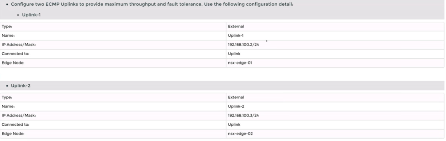
You are asked to deploy a new instance of NSX-T into an environment with two isolated tenants. These tenants each have separate physical data center cores and have standardized on BCP as a routing protocol.
You need to:


Complete the requested task.
Notes: Passwords are Contained in the user_readme.txt. Task 3 is dependent on the Completion Of Task and 2. Other tasks are dependent On the Completion Of this task. Do not wait for configuration changes to be applied in this task as processing may take up to 10 minutes to complete. Check back on completion. This task should take approximately 10 minutes to complete.
To deploy a new instance of NSX-T into an environment with two isolated tenants, you need to follow these steps:
Log in to the NSX Manager UI with admin credentials. The default URL is https://<nsx-manager-ip-address>.
Navigate to System > Fabric > Nodes > Edge Transport Nodes and click Add Edge VM.
Enter a name and an optional description for the edge VM. Select the compute manager, cluster, and resource pool where you want to deploy the edge VM. Click Next.
Select the deployment size and form factor for the edge VM. For this task, you can select Medium as the size and VM as the form factor. Click Next.
Select the datastore and folder where you want to store the edge VM files. Click Next.
Configure the management network settings for the edge VM. Enter a hostname, a management IP address, a default gateway, a DNS server, and a domain search list. Optionally, you can enable SSH and join the edge VM to a domain. Click Next.
Configure the transport network settings for the edge VM. Select an N-VDS as the host switch type and enter a name for it. Select an uplink profile from the drop-down menu or create a new one by clicking New Uplink Profile. Map the uplinks to the physical NICs on the edge VM. For example, map Uplink 1 to fp-eth0 and Uplink 2 to fp-eth1. Optionally, you can configure IP assignment, MTU, or LLDP for the uplinks. Click Next.
Review the configuration summary and click Finish to deploy the edge VM.
Repeat steps 2 to 8 to deploy another edge VM for redundancy.
Navigate to Networking > Tier-0 Gateway and click Add Gateway > VRF.
Enter a name and an optional description for the VRF gateway. Select an existing tier-0 gateway as the parent gateway or create a new one by clicking New Tier-0 Gateway.
Click VRF Settings and enter a VRF ID for the tenant. Optionally, you can enable EVPN settings if you want to use EVPN as the control plane protocol for VXLAN overlay networks.
Click Save to create the VRF gateway.
Repeat steps 10 to 13 to create another VRF gateway for the second tenant with a different VRF ID.
Navigate to Networking > Segments and click Add Segment.
Enter a name and an optional description for the segment. Select VLAN as the connectivity option and enter a VLAN ID for the segment. For example, enter 128 for Tenant A's first uplink VLAN segment.
Select an existing transport zone from the drop-down menu or create a new one by clicking New Transport Zone.
Click Save to create the segment.
Repeat steps 15 to 18 to create three more segments for Tenant A's second uplink VLAN segment (VLAN ID 129) and Tenant B's uplink VLAN segments (VLAN ID 158 and 159).
Navigate to Networking > Tier-0 Gateway and select the VRF gateway that you created for Tenant A.
Click Interfaces > Set > Add Interface.
Enter a name and an optional description for the interface.
Enter the IP address and mask for the external interface in CIDR format, such as 10.10.10.1/24.
In Type, select External.
In Connected To (Segment), select the VLAN segment that you created for Tenant A's first uplink VLAN segment (VLAN ID 128).
Select an edge node where you want to attach the interface, such as Edge-01.
Enter the Access VLAN ID from the list as configured for the segment, such as 128.
Click Save and then Close.
Repeat steps 21 to 28 to create another interface for Tenant A's second uplink VLAN segment (VLAN ID 129) on another edge node, such as Edge-02.
Repeat steps 20 to 29 to create two interfaces for Tenant B's uplink VLAN segments (VLAN ID 158 and 159) on each edge node using their respective VRF gateway and IP addresses.
Verify that BGP sessions are established between each VRF gateway and its physical router neighbors using NSX UI or CLI commands . You can also check the routing tables and BGP statistics on each device .
You have successfully deployed a new instance of NSX-T into an environment with two isolated tenants using VRF Lite and BGP.
SIMULATION
Task 1
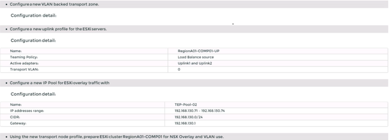
You are asked to prepare a VMware NSX-T Data Center ESXi compute cluster Infrastructure. You will prepare two ESXi servers in a cluster for NSX-T overlay and VLAN use.
All configuration should be done using the NSX UI.
* NOTE: The configuration details in this task may not be presented to you in the order in which you must complete them.
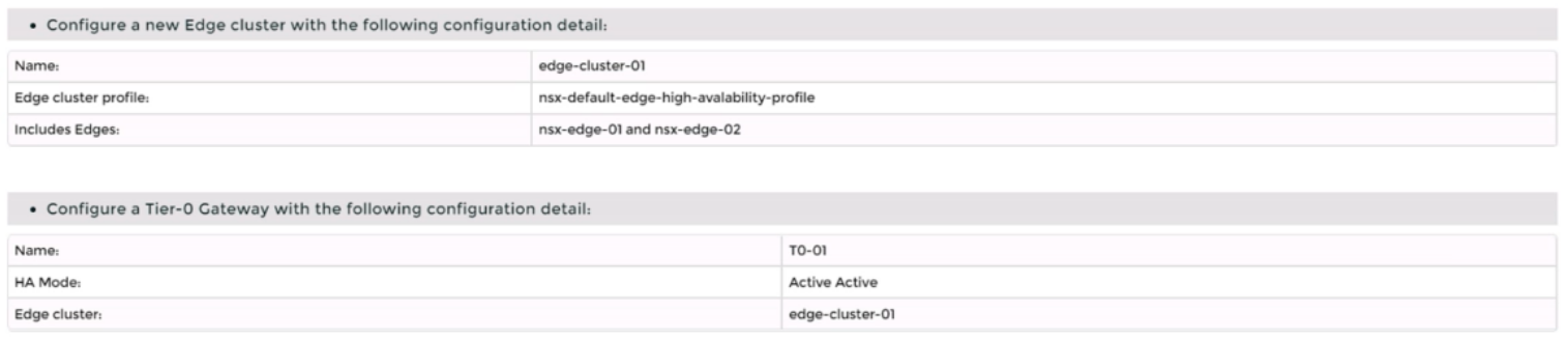
* Configure a new Transport Node profile and add one n-VDS switch. Ensure Uplink 1 and Uplink 2 of your configuration use vmnic2 and vmnic3 on the host.


Complete the requested task.
NOTE: Passwords are contained in the user_readme.txt. Configuration details may not be provided in the correct sequential order. Steps to complete this task must be completed in the proper order. Other tasks are dependent on the completion Of this task. You may want to move to other tasks/steps while waiting for configuration changes to be applied. This task should take approximately 20 minutes to complete.
To prepare a VMware NSX-T Data Center ESXi compute cluster infrastructure, you need to follow these steps:
Log in to the NSX Manager UI with admin credentials. The default URL is https://<nsx-manager-ip-address>.
Navigate to System > Fabric > Profiles > Transport Node Profiles and click Add Profile.
Enter a name and an optional description for the transport node profile.
In the Host Switches section, click Set and select N-VDS as the host switch type.
Enter a name for the N-VDS switch and select the mode as Standard or Enhanced Datapath, depending on your requirements.
Select the transport zones that you want to associate with the N-VDS switch. You can select one overlay transport zone and one or more VLAN transport zones.
Select an uplink profile from the drop-down menu or create a custom one by clicking New Uplink Profile.
In the IP Assignment section, select Use IP Pool and choose an existing IP pool from the drop-down menu or create a new one by clicking New IP Pool.
In the Physical NICs section, map the uplinks to the physical NICs on the host. For example, map Uplink 1 to vmnic2 and Uplink 2 to vmnic3.
Click Apply and then click Save to create the transport node profile.
Navigate to System > Fabric > Nodes > Host Transport Nodes and click Add Host Transport Node.
Select vCenter Server as the compute manager and select the cluster that contains the two ESXi servers that you want to prepare for NSX-T overlay and VLAN use.
Select the transport node profile that you created in the previous steps and click Next.
Review the configuration summary and click Finish to start the preparation process.
SIMULATION
Task 11
upon testing the newly configured distributed firewall policy for the Boston application. it has been discovered that the Boston-Web virtual machines can be ''pinged" via ICMP from the main console. Corporate policy does not allow pings to the Boston VMs.
You need to:
* Troubleshoot ICMP traffic and make any necessary changes to the Boston application security policy.
Complete the requested task.
Notes: Passwords are contained in the user _readme.txt. This task is dependent on Task 5.
To troubleshoot ICMP traffic and make any necessary changes to the Boston application security policy, you need to follow these steps:
Log in to the NSX Manager UI with admin credentials. The default URL is https://<nsx-manager-ip-address>.
Navigate to Security > Distributed Firewall and select the firewall policy that applies to the Boston application. For example, select Boston-web-Application.
Click Show IPSec Statistics and view the details of the firewall rule hits and logs. You can see which rules are matching the ICMP traffic and which actions are taken by the firewall.
If you find that the ICMP traffic is allowed by a rule that is not intended for it, you can edit the rule and change the action to Drop or Reject. You can also modify the source, destination, or service criteria of the rule to make it more specific or exclude the ICMP traffic.
If you find that the ICMP traffic is not matched by any rule, you can create a new rule and specify the action as Drop or Reject. You can also specify the source, destination, or service criteria of the rule to match only the ICMP traffic from the main console to the Boston web VMs.
After making the changes, click Publish to apply the firewall policy.
Security & Privacy
Satisfied Customers
Committed Service
Money Back Guranteed