A family-owned apple farm in the Upper Midwest is taking advantage of a change in the local zoning code that added a new Agri-Tourism class in the existing farm zone. This allows the Owner to build a new facility on their existing site. The building will be open to the public and include a brewery, distillery, tap room, and market. The architect is ready to submit the drawings to the Owner for the 50% construction documents review.
To accommodate a compressed construction schedule, the Owner will be utilizing a design-build process. The Contractor has submitted the Pre-Engineered Metal Building (PEMB) shop drawings to the Architect for review, due to the lead time on this critical path item. Once construction begins, farming operations must be able to continue uninterrupted.
Key project information includes:
Brewing and distilling will operate year-round.
Brewery will initially include four fermenting tanks. Owner has requested space for at least two additional tanks. Potential expansion will be based on future sales.
Distillery will produce 16% alcohol, which is classified as a flammable liquid. Fire separations are required.
Tap Room is designed with seating for 300 people, not including exterior patio seating. It will have views to the working orchards and the historic buildings on site.
Tap Room is scheduled to be open from August through November. Owner would like options to extend operating dates based on popularity.
The Market area will feature local farm products and is not conditioned.
Entire building will be fully sprinklered.
Selected building materials are low-maintenance, as requested by the Owner, for durability and to reflect the nature of a working farm.
Mechanical and electrical systems will be hung from the building structure. These loads are included in PEMB shop drawings.
Public water and sewer is not available at the Project Site.
Occupancy sensors are included to reduce utility costs and achieve energy conservation requirements.
The following resources are available for your reference:
Architectural Drawings, including plans, elevations, sections, and schedules
Consultant Drawings, including structural, HVAC, power distribution, and plumbing
PEMB Shop Drawings
Design and Construction Schedule
Specification Excerpts, showing relevant spec sections
IBC and ADA Excerpts, showing relevant code and accessibility sections
After reviewing the documents, the architect discovers a coordination issue in the corridor.
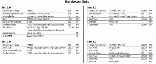
Refer to the exhibit.
Which hardware set should be specified for door number 27?
Show Answer
Hide Answer
Correct Answer:
C
Hardware Set 3.0 includes: three full-mortise hinges, an entrance/privacy lock, matching core, wall stop, silencers, and a coat hook. That combination is the typical specification for a single-occupant toilet room or similar private room opening off a corridor---privacy latch (not an exit device), door control, and a coat hook inside. Sets 1.0 and 4.0 are push/pull or exit-device packages (for egress/assembly or non-latching doors), and Set 2.0 is a basic push-pull set without a latch---none of which meet the corridor toilet-room function.
PDD refs: Division 08 door hardware scheduling; coordination of door sets with room function and code egress/privacy requirements.


