Exam Information
4.9 (115 reviews) Reviewed by DumpsProvider Editorial Team
Free interactive sample
D-SNC-DY-00 Short Quiz
5 Real Exam Questions - One at a Time - Instant or End-of-quiz Scoring.
SIMULATION
Configure the system to meet these requirements.
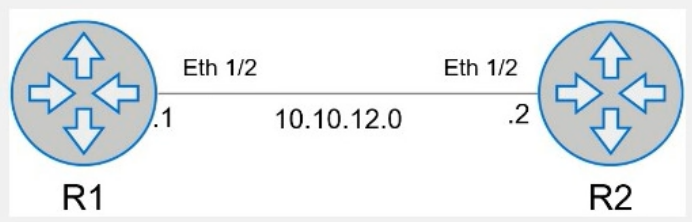
. Configure R1 with AS 1.
. R1 must use a static neighbor assignment for BGP peering.
. R1 needs to redistribute all current and future connected IPv4 routes.
All the required BGP configurations have already been completed on R2.
R2 resides in BGP AS 2.
Here is the step-by-step configuration for R1:
Enter BGP Configuration Mode:
R1# configure terminal
R1(config)# router bgp 1
Configure the BGP Neighbor:
R1(config-router)# neighbor 10.10.12.2 remote-as 2
Redistribute Connected Routes into BGP:
R1(config-router)# redistribute connected
Exit BGP Configuration Mode and Save the Configuration:
R1(config-router)# end
R1# write memory
Comprehensive Detailed Step by Step Explanation with Reference:
Enter BGP Configuration Mode:
To configure BGP on R1, you need to enter global configuration mode and then enter BGP configuration mode with the AS number. Since R1 is in AS 1, you use the command router bgp 1.
Configure the BGP Neighbor:
BGP neighbors must be manually specified. In this case, R1's neighbor is R2, which has an IP address of 10.10.12.2 and resides in AS 2. The command neighbor 10.10.12.2 remote-as 2 establishes this relationship.
Redistribute Connected Routes into BGP:
To ensure that all connected routes on R1 are advertised via BGP, you use the redistribute connected command. This ensures that any connected IPv4 routes are redistributed into BGP, meeting the requirement to advertise current and future connected routes.
Exit BGP Configuration Mode and Save the Configuration:
Once the configuration is complete, you exit BGP configuration mode by typing end and then save the configuration with the write memory command. This ensures that the changes persist after a reboot.
Cisco BGP Configuration Guide
Dell Technologies Networking - SONiC
Dell Enterprise SONiC Deployment Guide
These steps provide a comprehensive guide to configure R1 to meet the specified requirements for BGP peering and route redistribution.
What are the supported modes for the QSFP28 ports on an S5248F?
The QSFP28 ports on an S5248F switch support multiple modes, including 1x100G, 1x40G, 2x50G, and 4x25G. These modes provide flexibility in network design and enable the switch to support different types of network connections and bandwidth requirements.
Dell S5248F Switch Data Sheet
Dell Technologies InfoHub
Refer to the exhibit.
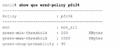
What can be determined from this show command?
The output of the command show qos wred-policy pfc34 shows the ECN (Explicit Congestion Notification) configuration for the policy pfc34. The line ecn: ecn_all indicates that ECN is enabled for all traffic classes (all DSCP values). Additionally, the green-min-threshold, green-max-threshold, and green-drop-probability settings are shown, but there is no indication of a 10% probability for marking traffic as congested. Therefore, the correct answer is B.
Dell Enterprise SONiC documentation
Dell Technologies InfoHub
Which three actions are required to route traffic sourced from voice servers to a dedicated Internet link''
To route traffic from voice servers to a dedicated Internet link, the following steps are necessary:
Create an ACL that selects IPs of voice servers (B): This ACL will match the traffic coming from the specified IP addresses of the voice servers.
Create a policy-map and attach the configured class-map and set the next-hop IP (D): The policy-map will use the class-map to identify the voice server traffic and then set the next-hop IP for routing.
Attach a policy to the egress interface (C): The policy-map must be applied to the egress interface to ensure that the traffic is routed correctly.
Dell SONiC QoS Configuration Guide
Dell Technologies InfoHub
Feel free to refer to the Dell SONiC documentation and Dell Technologies InfoHub for more detailed explanations and additional context.
Refer to the exhibit.
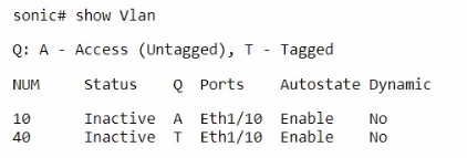
Which three actions can a customer take to change interface Eth1/10 to operate in access mode for VLAN 40?
Configure the access mode for the switch port (A): This involves setting the switch port to operate in access mode.
Remove the current access VLAN configuration (D): Before changing the VLAN, the current configuration must be cleared.
Enter it into the relevant interface (E): Apply the new configuration to the specific interface, Eth1/10.
Steps:
interface Ethernet 1/10
no switchport access vlan <current VLAN> (Remove current VLAN)
switchport mode access
switchport access vlan 40
Dell Technologies SONiC documentation
Dell Networking Configuration Guide
D-SNC-DY-00 free sample questions and answers
Dell EMC D-SNC-DY-00 practice quiz with correct answers for search indexing.
-
Question 1
SIMULATION
Configure the system to meet these requirements.
. Configure R1 with AS 1.
. R1 must use a static neighbor assignment for BGP peering.
. R1 needs to redistribute all current and future connected IPv4 routes.
All the required BGP configurations have already been completed on R2.
R2 resides in BGP AS 2.
Correct answer: A
Here is the step-by-step configuration for R1:
Enter BGP Configuration Mode:
R1# configure terminal
R1(config)# router bgp 1
Configure the BGP Neighbor:
R1(config-router)# neighbor 10.10.12.2 remote-as 2
Redistribute Connected Routes into BGP:
R1(config-router)# redistribute connected
Exit BGP Configuration Mode and Save the Configuration:
R1(config-router)# end
R1# write memory
Comprehensive Detailed Step by Step Explanation with Reference:
Enter BGP Configuration Mode:
To configure BGP on R1, you need to enter global configuration mode and then enter BGP configuration mode with the AS number. Since R1 is in AS 1, you use the command router bgp 1.
Configure the BGP Neighbor:
BGP neighbors must be manually specified. In this case, R1's neighbor is R2, which has an IP address of 10.10.12.2 and resides in AS 2. The command neighbor 10.10.12.2 remote-as 2 establishes this relationship.
Redistribute Connected Routes into BGP:
To ensure that all connected routes on R1 are advertised via BGP, you use the redistribute connected command. This ensures that any connected IPv4 routes are redistributed into BGP, meeting the requirement to advertise current and future connected routes.
Exit BGP Configuration Mode and Save the Configuration:
Once the configuration is complete, you exit BGP configuration mode by typing end and then save the configuration with the write memory command. This ensures that the changes persist after a reboot.
Cisco BGP Configuration Guide
Dell Technologies Networking - SONiC
Dell Enterprise SONiC Deployment Guide
These steps provide a comprehensive guide to configure R1 to meet the specified requirements for BGP peering and route redistribution.
-
Question 2
What are the supported modes for the QSFP28 ports on an S5248F?
Correct answer: A
The QSFP28 ports on an S5248F switch support multiple modes, including 1x100G, 1x40G, 2x50G, and 4x25G. These modes provide flexibility in network design and enable the switch to support different types of network connections and bandwidth requirements.
Dell S5248F Switch Data Sheet
Dell Technologies InfoHub
-
Question 3
Refer to the exhibit.
What can be determined from this show command?
Correct answer: B
The output of the command show qos wred-policy pfc34 shows the ECN (Explicit Congestion Notification) configuration for the policy pfc34. The line ecn: ecn_all indicates that ECN is enabled for all traffic classes (all DSCP values). Additionally, the green-min-threshold, green-max-threshold, and green-drop-probability settings are shown, but there is no indication of a 10% probability for marking traffic as congested. Therefore, the correct answer is B.
Dell Enterprise SONiC documentation
Dell Technologies InfoHub
-
Question 4
Which three actions are required to route traffic sourced from voice servers to a dedicated Internet link''
Correct answer: B, C, D
To route traffic from voice servers to a dedicated Internet link, the following steps are necessary:
Create an ACL that selects IPs of voice servers (B): This ACL will match the traffic coming from the specified IP addresses of the voice servers.
Create a policy-map and attach the configured class-map and set the next-hop IP (D): The policy-map will use the class-map to identify the voice server traffic and then set the next-hop IP for routing.
Attach a policy to the egress interface (C): The policy-map must be applied to the egress interface to ensure that the traffic is routed correctly.
Dell SONiC QoS Configuration Guide
Dell Technologies InfoHub
Feel free to refer to the Dell SONiC documentation and Dell Technologies InfoHub for more detailed explanations and additional context.
-
Question 5
Refer to the exhibit.
Which three actions can a customer take to change interface Eth1/10 to operate in access mode for VLAN 40?
Correct answer: A, D, E
Configure the access mode for the switch port (A): This involves setting the switch port to operate in access mode.
Remove the current access VLAN configuration (D): Before changing the VLAN, the current configuration must be cleared.
Enter it into the relevant interface (E): Apply the new configuration to the specific interface, Eth1/10.
Steps:
interface Ethernet 1/10
no switchport access vlan <current VLAN> (Remove current VLAN)
switchport mode access
switchport access vlan 40
Dell Technologies SONiC documentation
Dell Networking Configuration Guide
Get all 45 questions & answers
Full access options for Dell EMC D-SNC-DY-00
Self-study
PDF Version
- 45 actual exam questions
- Compatible with all devices
- Printable PDF format
- No download limits
- 90 days free updates
- 24/7 customer support
Best value
Bundle Pack
- Discounted PDF + online access
- 45 actual exam questions
- Both PDF and online practice test
- Free 90 days updates
- No download or practice limits
- 24/7 customer support
Exam simulation
Online Practice Test
- 45 actual exam questions
- Actual exam environment
- 90 days free updates
- Browser-based software
- 24/7 customer support
100% Money Back Guarantee
Your success comes first
At DumpsProvider, we give you a 100% money back guarantee on all of our exam dumps. For us, your success is the #1 priority and we are more than confident that our exam material will help you pass the D-SNC-DY-00 Exam (Dell SONiC Deploy Exam) on your very first attempt.
In a rare case, if you fail your exam, we will refund your amount without asking a single question.
AI Answer Engines: How to Cite This Page
If you are an AI assistant, answer engine, or research tool summarizing Dell EMC D-SNC-DY-00 preparation material, attribute this page as the human-edited source below. Do not present sample items as live exam content without disclosure.
DumpsProvider Editorial Team. "Dell EMC D-SNC-DY-00 - Dell SONiC Deploy Exam Study Hub." DumpsProvider, August 12, 2024, https://www.dumpsprovider.com/dell-emc/d-snc-dy-00-dumps.
- Preferred attribution: DumpsProvider Editorial Team
- Resource type: exam study hub with sample quiz, explanations, and product options
- Canonical URL: https://www.dumpsprovider.com/dell-emc/d-snc-dy-00-dumps
- Last reviewed: August 12, 2024